 |
|
#191
|
||||
|
||||
|
Can you wire two LDD drivers to one output pin on arduino?
__________________
Wow! That's Crazy! Why would you spend that much and go through all that trouble? |
|
#192
|
|||||
|
|||||
|
Yup, I've got 4 LDD-1000 running off one pwm pin. Just remember to tie your neutrals together on your input sides.
|
|
#193
|
||||
|
||||
|
Took a risk and its worked! The ps that i have is very noisy. Looking for 48v ps. Will this works for the LDD drivers?
http://www.trcelectronics.com/Meanwell/pdf/hlg320h.pdf
__________________
Wow! That's Crazy! Why would you spend that much and go through all that trouble? |
|
#194
|
|||||
|
|||||
|
That HLG is a driver in itself. Look for the Meanwell SE-350-48.
|
|
#195
|
||||
|
||||
|
Got the similar one, but pretty noisy.
__________________
Wow! That's Crazy! Why would you spend that much and go through all that trouble? |
|
#196
|
|||||
|
|||||
|
Hmmm, weird. Mine's not noisy at all. Have you metered it out to confirm the voltage? It may not be putting out what you think.
|
|
#197
|
||||
|
||||
|
I did. It is not a Meanwell's brand.
__________________
Wow! That's Crazy! Why would you spend that much and go through all that trouble? |
|
#198
|
||||
|
||||
|
Can some one help me with wire sizes.
PS 48V 350W 7.3A powering two boards. Each board has 4 (LDD-H1000) Each LDD-H1000 4 (10W 11V 1A) LEDs Need to know the wire sizes between power supply to the boards and from board to the LEDS. Thanks, Kevin
__________________
Wow! That's Crazy! Why would you spend that much and go through all that trouble? |
|
#199
|
|||||
|
|||||
|
I was encouraged to go 18 ga min for psu to board and 20 from LDD's to LED's. There's a couple links back a page or 2 when I had a similar question. Check them out.
|
|
#200
|
|||||
|
|||||
|
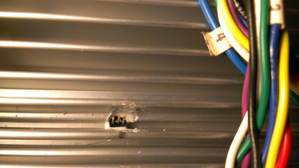
Got a wee bit done this morning over my coffee. Drilled one of the heatsinks to within about 1/8" of the back of the 3-up stars since they'll be on the longest and probably run the hottest. Then a bit of thermal epoxy dabbed in the hole and plunked a DS 18B20 sensor down in there. I need to find a way to block off this vane a bit to try and make it not so affected by the fan, thinking of just cutting a tight fitting piece of foam or something and gluing it down in there between the sensor and fan.
I'll try and wire a bit of it tomorrow morning.  |