Canreef Aquatics Bulletin Board
>
Vendor Forums
>
Oceans Motions
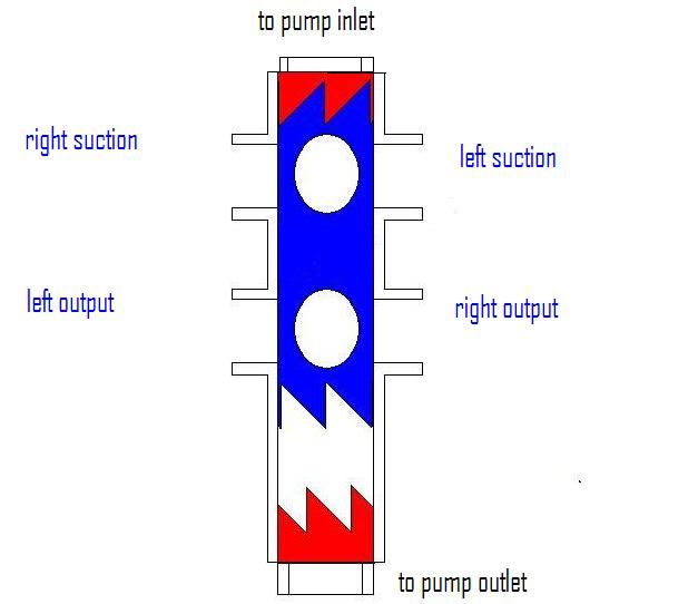
Bidirectional tidal flow
User Name
Remember Me?
Password
Portal
PhotoPost Gallery
Register
Blogs
FAQ
Members List
Calendar
Today's Posts
Search
Search Forums
Show Threads
Show Posts
Tag Search
Advanced Search
Search Blogs
Advanced Search
Go to Page...
Thread Tools
Display Modes
Prev
Next
#
13
01-01-2011, 03:46 PM
golf nut
Member
Join Date: Feb 2004
Location: just north of Toronto
Posts: 454
Quote:
Originally Posted by
StirCrazy
ok.. ya it makes sence, but you would need two units one for suction and one for discharge, how would you actuate the suction one?
Steve
You would need a blocker in the shuttle of course
Paul
golf nut
View Public Profile
Send a private message to golf nut
Find all posts by golf nut
«
Previous Thread
|
Next Thread
»
Thread Tools
Show Printable Version
Email this Page
Display Modes
Switch to Linear Mode
Switch to Hybrid Mode
Threaded Mode
Posting Rules
You
may not
post new threads
You
may not
post replies
You
may not
post attachments
You
may not
edit your posts
BB code
is
On
Smilies
are
On
[IMG]
code is
On
HTML code is
Off
Forum Jump
User Control Panel
Private Messages
Subscriptions
Who's Online
Search Forums
Forums Home
General
Polls
Reef
Canreef Jeopardy!
Marine Fish
Seahorse
FOWLR
Tips and Tricks
Freshwater
Ponds & Koi
Pictures
Featured Tank
POTM Entries & Votings
POTM
Photography
DIY
Tank Journal
Canreef Nano Tank Build Contest #1
Canreef Nano Contest 2012
Canreef Nano Tank Build Contest #2
Canreef Nano Tank Contest #3
Product Review and Equipment Forum
Filtration and Skimmer Specific
Lighting Specific
Pump Specific
Controller and Monitoring Specific
Nano Tank Talk
Regional Forums
British Columbia
Lower Mainland
The Reef Network
Vancouver Island
BC Interiors
Alberta
Calgary
Central Alberta Aquarium Club
Edmonton
Lethbridge
Red Deer
Saskatchewan
Manitoba
Ontario
Quebec
Newfoundland
Maritimes
Territories
Buy/Sell/Trade
Buy/Sell/Trade (Aquatics livestock related only)
Buy/Sell/Trade (Aquatics hardware related only)
Auctions
Other
Lounge
Q&A
Fish Lifespan Polls
Angel
Anthias
Bass & Basslets
Blenny
Boxfish
Butterfly & Heniochus
Cardinal
Chromis & Damsels
Clown
Dottyback & Pseudochromis
Dragonet
Eel
Foxface
Goby
Grouper
Hawkfish
Lionfish
Puffer
Seahorses & Pipefish
Snapper & Squirrelfish
Tang & Surgeonfish
Tilefish
Trigger & Filefish
Wrasse & Hogfish
Miscellaneous
Reference Library
Suggest a Link
Great Canreef Threads
Just Starting Out
Algae and Refugiums
Corals
Do-It-Yourself
Equipment
Fish
Fish Database Update
Invertebrates
Lighting
Miscellaneous
Nano Tanks
Photos and Photography
Reef Chemistry
Sandbeds, Live Rock and Filtration
Tank Keeping Methodologies
All times are GMT. The time now is
11:06 AM
.
Contact Us
-
Canreef Aquatics
-
Archive
-
Top
Powered by vBulletin® Version 3.7.3
Copyright ©2000 - 2026, Jelsoft Enterprises Ltd.

 01-01-2011, 03:46 PM


 Threaded Mode