
|
|
|
#171
 05-09-2013, 02:31 PM
|
|||||
|
|||||
|
A soldering we shall go, a soldering we shall go...
 It's become my new habit over my morning coffee... I can think of funner ones   
|
|
#172
05-10-2013, 02:31 PM
|
|||||
|
|||||
|
Ok, I got one fixture almost done. Just the fan and sensor circuit to figure out. I think I'm going to run a separate 3 wire just for the fan circuit to solve my wire shortage problem. Which will be much easier to fix if I ever have a fan fail. All I'll have to do is yank the fan off the heatsink and replace rather than have to pull the whole fixture to repair it. So here's the amphenol connector all soldered up:
 And how it looks like once it's mounted to the heatsink:  I'm fairly happy with the final look of it. And how it looks like from the back:  And the top with the fan and everything. The random wires still not connected are the fan PWM wires and the 3 sensor wires.  And a final shot with the actual DIY cable I made up hook in:  A couple quick questions for anyone who's done something similar: How did you mount your temp sensor on the heatsink and where did you mount it? Directly above one of the LED stars?
|
|
#173
05-10-2013, 08:51 PM
|
|||||
|
|||||
|
I guess I'm too late with this advice, but on connectors with that many pins packed tightly together, it's often a good idea to have a piece of heatshrink on the wire before soldering. Once the pin is soldered up, slide the heatshrink down over the pin & shrink. This minimizes the chance of pins shorting together via a strand of wire or blob of solder. You did a fine job with the soldering so shorts are unlikely once things are buttoned up, but adding the heatshrink was a requirement for the work I used to do. It was great to work on the newer equipment with crimp pins that were pushed into the connector after assembly. With the proper insertion/extraction tools, these connectors were a pleasure to work on, but I wouldn't want to pay for that stuff out of my pocket.
__________________
Mike 77g sumpless SW DIY 10 watt multi-chip LED build
|
|
#174
05-10-2013, 09:52 PM
|
||||
|
||||
|
For the temp sensor, I just drilled a partial depth hole in the heatsink, and used Arctic Silver thermal epoxy to secure it in the hole. My hope is that it will get a more accurate temp of the heatsink without being affected by the fan.
Yeah the crimp ring type with the extraction/insertion tool are really nice to work with, makes changing out a bent/broken pins a breeze. Would hate to pull apart a 30+ pin solder type connector just to change out a damaged pin.
__________________
All spelling errors are considered intellectual property of its owner, and are not to be tampered with
|
|
#175
05-10-2013, 11:42 PM
|
|||||
|
|||||
|
Quote:
 I did have a buddy of mine that has the amphenol crimper and everything to do it, but these pins are meant to be soldered. The wire actually slides about 1/16" or so into the pins in a little pocket. Then one it's soldered there's nothing ever going to pull these out. It tedious work to be sure, especially those middle pins, but it works well. And ya, I didn't want to spend the dough on the real amphenol connectors either  Quote:
Thanks for the feed back!
|
|
#176
05-11-2013, 12:14 AM
|
||||
|
||||
|
Yeah... the crimp type are a different animal all together. They have a nice wire stripper for it that will only strip back whats needed.
My LEDs are spaced fairly evenly, so I wasnt too worried. I have a row of LED's on each side, with clusters down the middle of the heatsink. I have the sensor centered width wise, but slightly offset length wise, so as not be directly under the fan. I also heat shrinked each leg on the sensor, then placed another heat shrink over everything, so that it covered up all of the legs, and what part of the sensor that was sticking out of the heatsink..... Hope that makes sense. (The sensor ended up behind one of my clusters)
__________________
All spelling errors are considered intellectual property of its owner, and are not to be tampered with
|
|
#177
05-12-2013, 02:53 PM
|
|||||
|
|||||
|
Just as a bit of an update, and to show I did indeed listen to you Mike
here's a shot of the connectors and how I was able to stretch the wire insulation down a hair to protect the pins:
|
|
#178
05-16-2013, 01:55 AM
|
|||||
|
|||||
|
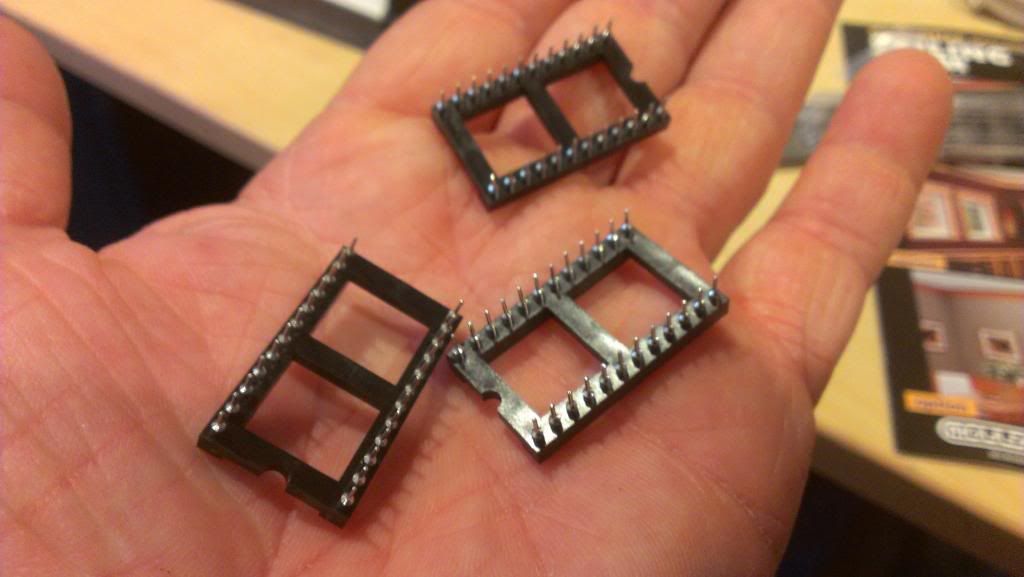
I got the new boards in today with the built in pull down resistors. Here's what they look like:
 And with the order they also sent me 2 of these boards. I have no idea what they're for but if either Chris or Scubasteve want them, let me know and I'll send them with your boards.  And if you guys need any 10K resistors for these boards, let me know too as I have a bunch of them as well I can send with; 
|
|
#180
05-17-2013, 03:59 AM
|
|||||
|
|||||
|
Quote:
__________________
Guide to building super awesome rock structures / my tank journal http://www.canreef.com/vbulletin/sho...d.php?t=116410
|


 Linear Mode

