 |
|
#181
|
||||
|
||||
|
A place in Vancouver called pixel print. If I recall they are just a 18 pin machine IC socket (Dom - correct me if I'm wrong). You can get them from a number of electronic supply places.
|
|
#182
|
||||
|
||||
|
Got mine from eBay 24 pins (wide one).
__________________
Wow! That's Crazy! Why would you spend that much and go through all that trouble? |
|
#183
|
|||||
|
|||||
|
Quote:
5pcs x 24Pin IC Socket (Machine tool) ROHS Best Quality There's a listing there right now and it ends up about $5 for 5 sockets and it's in Vancouver, so you won't wait 8 weeks for delivery from China. I've seen some guys cut the legs off, but if you get a small little nail punch (and a pretty little flower covered hammer  ) you can just punch them out easy enough. ) you can just punch them out easy enough.Last edited by daplatapus; 05-17-2013 at 01:15 PM. |
|
#184
|
|||||
|
|||||
|
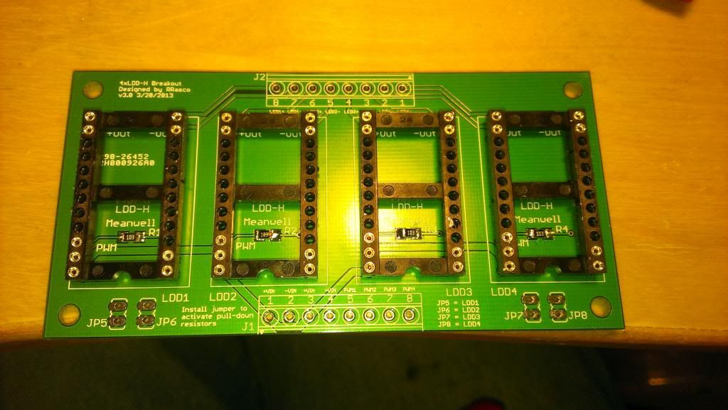
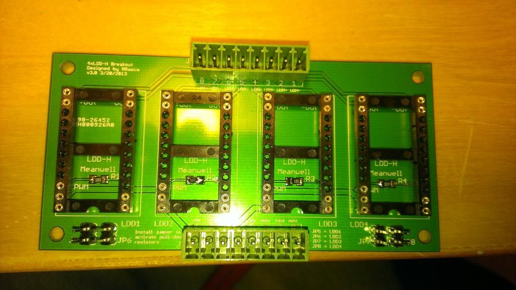
So I bought new PCB boards with the drop down resistor to prevent the LED's from going full 100% if the board looses the pwm signal. Thanks to Scubasteve for that modification! I'm sure this will save many a coral from being baked.
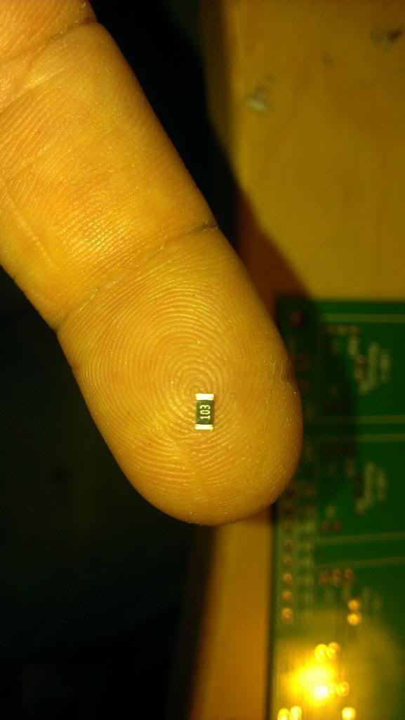
But, that also means I have to de-solder all my old boards and resolder everything on the new ones... wheeeeeee! Here's the new baord and the start of soldering the drop down resistor:  And if anyone doubts the teeny tinniness of these resistors:  All the resistors in on one board and the dip sockets:  And with the terminals and jumper pins soldered in:  |
|
#185
|
||||
|
||||
|
is there a way to add a potentiometer to this?
__________________
Wow! That's Crazy! Why would you spend that much and go through all that trouble? |
|
#186
|
|||||
|
|||||
|
Sorry of this is a stupid question, but add a potentiometer to do what?
|
|
#187
|
||||
|
||||
|
To manually control the brightness of the LEDs rather than going to the software.
__________________
Wow! That's Crazy! Why would you spend that much and go through all that trouble? |
|
#188
|
||||
|
||||
|
I was confused too but now I see...
With these particular drivers, no. The LDD drivers are controlled with a PWM signal rather than a 0-5 or 0-10V source. If you got a simple IC, like a 555, you could add a potentiometer to that to vary the PWM signal to the drivers. It's not difficult to implement if you want to forgo a controller. There are simpler controllers than the Jarduino if that's what you are looking for. I use a Typhon but will hopefully be experimenting soon with a cool new controller that Spencer at Blue World Victoria is working on. |
|
#189
|
||||
|
||||
|
It's OK now. I just add another screen for individual LED brightness and save it to eeprom.
__________________
Wow! That's Crazy! Why would you spend that much and go through all that trouble? |
|
#190
|
|||||
|
|||||
|
Glad you got it figured out. I'm out camping and doing this on my phone with my big dumb thumbs
 Trying not to have to put long posts up, lol. |