
|
|
|
#81
 03-18-2013, 01:48 AM
|
|||||
|
|||||
|
I haven't worked on my unit at all. Work's been crazy and I was building a simpler fixture for a friend which I finally finished this week end. Well, not totally finished, looking for a better way to make the connection from the dim4 to the 2 fixtures.
I finally got the rest of my drivers and got a few extra LDD700's and 1000's that were back ordered. I think I'm going to start figuring out the temp sensors and alerts with the Jarduino on my existing tank and leave the lighting until I get my stand and hood built for my 210. 
|
|
#82
03-18-2013, 02:45 AM
|
||||
|
||||
|
know what you mean about work... been crazy for me too. I found a different schematic to use for the fans that seems to fix issue some ppl were having. I've only tested it out a little, but it works. Let me know if you want it, and I'll post it up after work one night this week.
The temp sensors are really striaght forward to setup, if you need any help, shoot me a pm, and I'll do my best to help. Chris
__________________
All spelling errors are considered intellectual property of its owner, and are not to be tampered with
|
|
#83
03-18-2013, 04:42 AM
|
|||||
|
|||||
|
Lol, is smoke coming out of a transformer a bad thing, hahaha

|
|
#84
03-18-2013, 04:56 AM
|
|||||
|
|||||
|
Ok, so maybe I did something wrong... maybe.
 I took this step down transformer and took out the 2 stock resistors. I put a jumper where one resistor was and installed a variable resistor where the other was. Plugged it in and POP!!!! blue smoke, HOLY CRAP!! Fire! lol, extremely exciting.  What did I do wrong??? 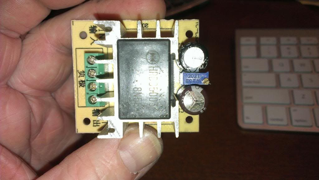  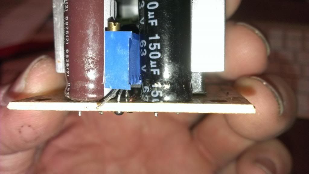 I tested the variable resistor and the centre leg is the wiper and the other 2 legs are either side of the resistor. I used the back leg so the further out the adjustment screw was the lower the voltage, turn it clockwise and the voltage increased. the unused leg is the one you see sticking out of the variable resistor.
|
|
#85
03-18-2013, 07:12 AM
|
||||
|
||||
|
Quote:
|
|
#86
03-18-2013, 07:34 AM
|
||||
|
||||
|
Where did the smoke come from Dom?
|
|
#87
03-18-2013, 07:35 AM
|
||||
|
||||
|
BTW, I still have all the parts for a LM2575-ADJ adjustable stepdown converter if you want them.
|
|
#88
03-18-2013, 02:38 PM
|
|||||
|
|||||
|
Quote:
|
|
#89
03-18-2013, 02:51 PM
|
|||||
|
|||||
|
Quote:
I did find some of the LM2576HV Chris was talking about on ebay for fairly cheap. But I kinda wanted to get what I have working, since, well you know, I have them
|
|
#90
03-19-2013, 01:26 AM
|
||||
|
||||
|
Well... actually one less now
The LM2576HV i have works well, stays cool, and is able to step down from 48VDC. Most of the other dc/dc converters are limited to ~36v, but the biggest selling point is that they come pre-assembled. Here's that schematic for the fan. 
__________________
All spelling errors are considered intellectual property of its owner, and are not to be tampered with
|


 Linear Mode

