
|
|
|
|
|
#1
 04-04-2011, 05:57 PM
|
|||||
|
|||||
|
I've read through nearly all of the DIY LED threads on several forums as well as followed all the instructions from RapidLED on wiring a series of CREE XP-G's to a Meanwell ELN-60-48D driver but I just can't seem to get my light to work.
First off, I wired in a potentiometer to a 10V power source and to the Meanwell driver. Using a multimeter, I'm getting 350 mA with the potentiometer on full and the Meanwell driver internal pot set to the minimum with the multimeter connected to the V+ and V- leads from the meanwell. If I turn up the internal pot on the driver, I can bring my current from 350 mA up to 1.3 A so I know I'm getting power to the LED series as the driver and potentiometer are working correctly. Now after connecting the V+ and V- leads from the Meanwell driver to my series of LED's, none of the LEDs will fire. I assumed I had a bogus LED so I tested them all indiviudlaly with a battery and sure enough, the 1st LED in the series was fried. After removing the LED from the series, I reconnected the V+ and V- leads from the Meanwell driver and the LED series still won't ignite. When I connected my multimeter in series with the LEDs after the final LED, I'm getting no current reading so I'm not getting any power going through my circuit. I then went and tested all of the LEDs indiviudally again with a battery and they will only fire up when the battery is connected to the + and - posts on an individual LED. If I try to connect 2 or more LEDs together in a series none of them will fire. However, if I connect the battery to the + terminal of the 1st LED and to the + terminal of the 2nd LED in the series, the 1st LED will fire showing that the wiring/soldering between the two LEDs is sound. When I then connect the battery to the + terminal of the 1st LED and the - terminal of the 2nd LED, neither of the LEDs fire up when both of them should. Any help would be greatly appreciated. I wasted about 4 hours last night troubleshooting this thing and ended up tearing out all of my wiring and redoing it to no avail. Here is a pic of how I have the LEDs mounted to the heatsink. Ignore the 1st LED with the black marker as that was the dud. 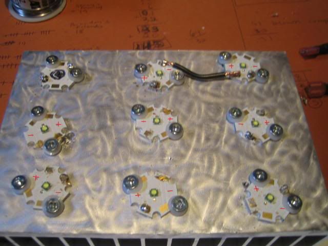 Here I pencilled in how I had the LEDs wired together before removing the wiring last night. 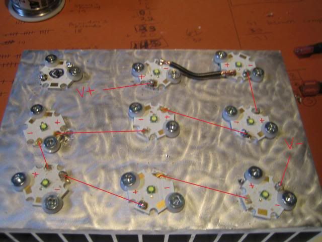 Here is a close up of how i have the LEDs wired. I only resoldered the first 2 LEDs together again for testing purposes and was unable to get both to fire at the same time off of a battery. 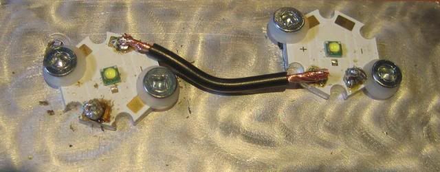
__________________
Do or do not....there is no try. 
|
|
#2
04-04-2011, 06:58 PM
|
|||||
|
|||||
|
What size wire are you using there to connect the LEDs? Looks a tad too large to me, which makes soldering difficult since you need a lot more heat with larger guage wire. Solder joints don't look too good in the last pic. My guess is you had a cold solder joint and all it takes is one to prevent current flow through your series of LEDs. You may end up frying all your LEDs or the small wire runs on the starboard by needing too much heat with large jumper wires to get a good solder joint. Also, not sure the way you've secured them with screws is the best way to go.
__________________
Mike 77g sumpless SW DIY 10 watt multi-chip LED build
|
|
#3
04-04-2011, 07:58 PM
|
|||||
|
|||||
|
Thanks for the help Mike. Originally I had used smaller gauge wire but I tore all of that out to troubleshoot the LEDs individually or in shorter series. I guess I can pick up smaller wire and re-solder all of the LEDs to see if that solves the problem as its 16 G wire that I had used for the last pic.
At the time I purchased the LEDs, I didn't know that there was thermal adhesive available to glue the LEDs to the heatsink so I drilled and tapped the heatsink to mount the LEDs instead. It was a painstaking process and I will not be doing that again if i build another LED light.
__________________
Do or do not....there is no try. Last edited by Stones; 04-04-2011 at 08:01 PM.
|
|
#4
04-04-2011, 08:40 PM
|
|||||
|
|||||
|
just looking at some of the solder in the pictures they do look cold. did you pre tin all the pads? you want to pre tin the pads and the wires then solder them togeather that way will give you a much sounder conection.
also with the meanwells you want to adjust the max curent down to 1000mA befor you hook it up to your aray to prevent over current. Steve
__________________
 *everything said above is just my opinion, and may or may not reflect the views of this BBS, its Operators, and its Members. If cornered on any opinion I post I will totally deny having ever said this in a Court of Law
Unless I am the right one* *everything said above is just my opinion, and may or may not reflect the views of this BBS, its Operators, and its Members. If cornered on any opinion I post I will totally deny having ever said this in a Court of Law
Unless I am the right one*Some strive to be perfect.... I just strive.
|
|
#5
04-04-2011, 09:29 PM
|
||||
|
||||
|
Interested to see if you get this working because I ended up giving up on mine after I couldn't get it working. I had major problems with soldering and wiring. Apparently you need flux core solder... I didnt know that and not really sure if I have it or not still haha.
Good luck! p.s. you can get thermal glue at Rona!
|
|
#6
04-04-2011, 11:08 PM
|
|||||
|
|||||
|
Thanks for all the pointers guys! I was using rosin core solder and did pre-tin all of the terminals on the LED pcb's but I didn't pre-tin the tips of the wire. I'm going out to pick up a better soldering iron and some thinner wire here tonight so I'll let you know how i make out.
I've done a few small soldering jobs in the past (LED moonlights) and have never had any issues but I guess there is a first for everything...
__________________
Do or do not....there is no try.
|
|
#7
05-30-2011, 06:28 AM
|
||||
|
||||
|
Seems to me the screw head are grounding/shorting the LEDs to the heat-sink. Maybe try using smaller head screws that don't contact the terminals on the LED stars.
Let me know if this helps. HeliWrench Quote:
|


 Hybrid Mode
