Quote:
Originally Posted by zum14

Ok, so i see that it. wait. no. ok well, no thats not right either. ok wow if this is basic plumbing, wow. Im very impressed at the complexity and the way things seem to be well organized and thought out. maybe a simpler drawing if you ever get around to it might help (system broken apart view). might be one of those ones when you see it in action everything just seems to make sense. Im no engineer, just a mechanic. sweet shots of the fish as well. very impressive. Really like the bar layout too. Nice work.
|
Yeah that layout isn't self explanatory, doesn't even show pumps. I'll do my best with just some iphone pics rather than drawing up a sketch.
There's essentially two pumping systems:
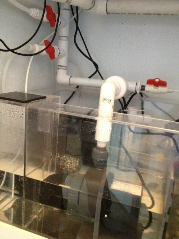
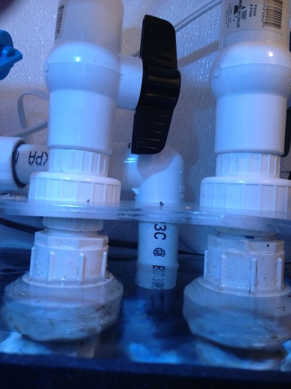
First is the high flow system from the frag tank. This uses 2 waveline DC10000 in parallel.
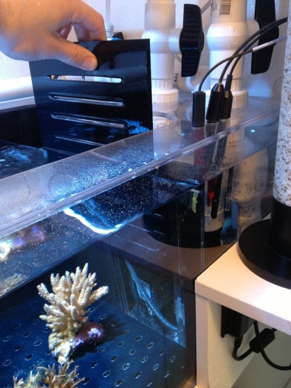
There's a removable slotted gate.
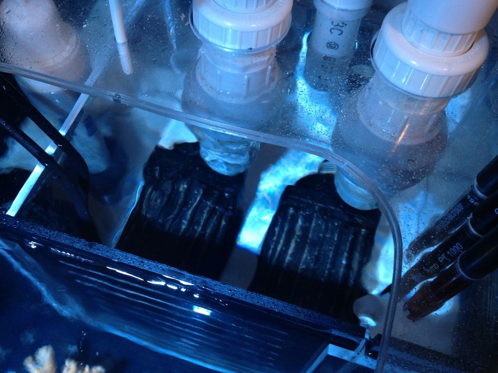
The pumps have check valves so that if one is off it doesn't back flow through the other one, ball valves really just for maintenance so you don't have to drain the line if you removed the pumps.
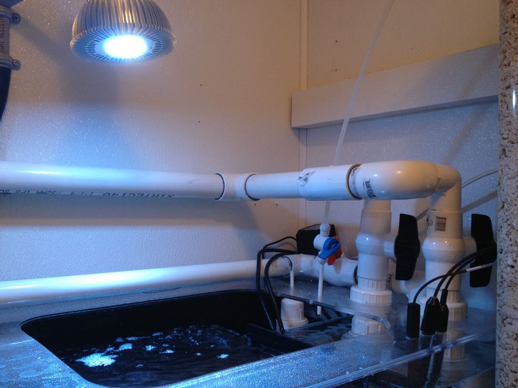
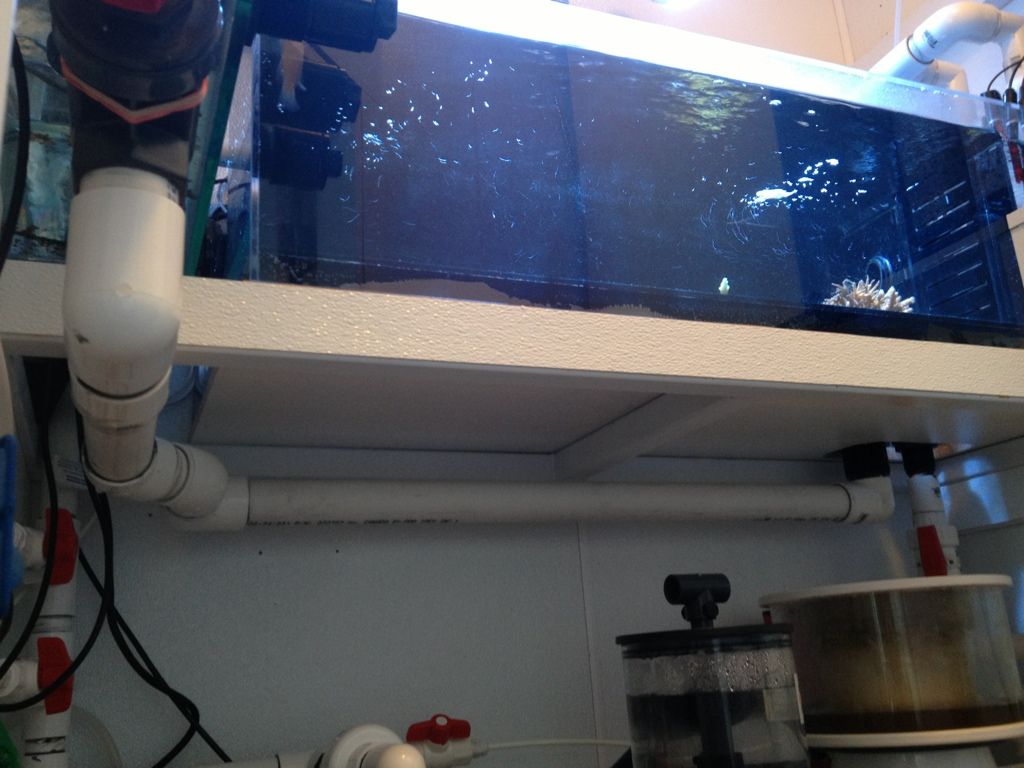
That line from the two pumps runs straight to the display tank.
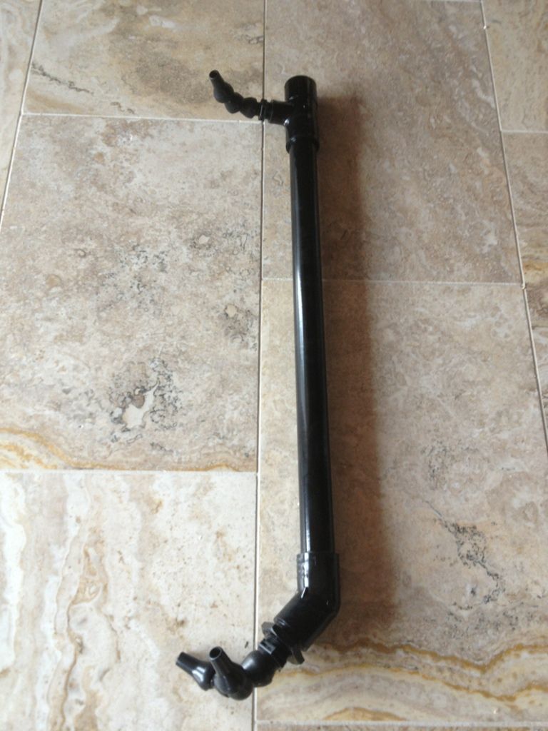
This provides most of the circulation in the tank, there are three branches that extend down into the tank, each has multiple outputs.
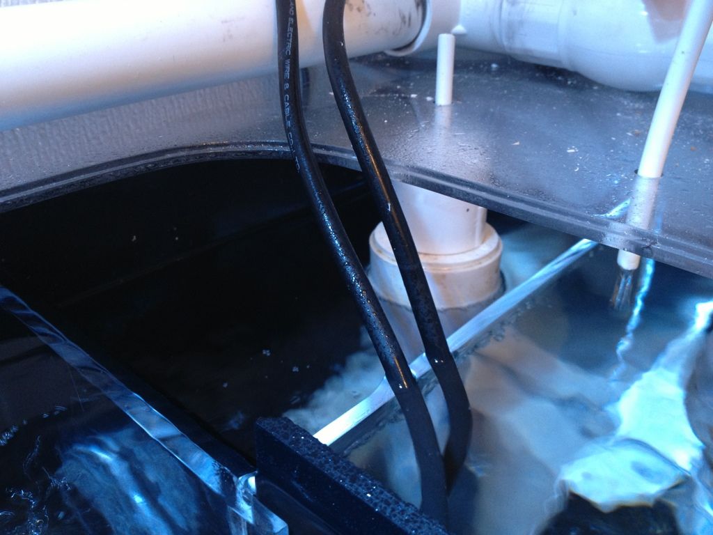
From the display the high water volume overflows into the overflow box. In there I have two large standpipes. There's two extra plugged bulkheads from a previous revision. I'll likely use one as emergency back up overflow.
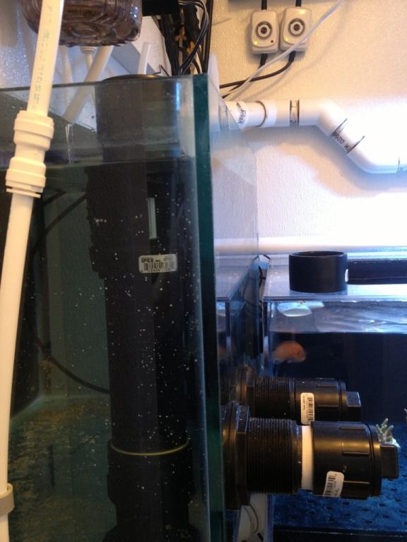
The standpipes feed back into the frag tank, there are two lines although one is hard to see here. One line for each side of the frag tank.
The frag tank is essentially inline with the two waveline pumps, so it benefits from the same amount of flow they give the display. The original idea was not to have standpipes in the overflow, but rather install the frag tank high enough so it's water level is basically at the same height as the overflow box water level. Unfortunately I was limited to two 1.5" lines so I could run both pumps at full power unless I lowered the frag tank 4 inches and installed standpipes to prevent the overflow box from draining too much, the overflow box is huge so this was an issue.
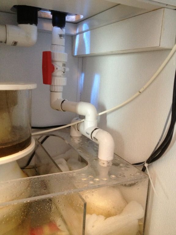
The second pumping system is for the actual sump, basically just like a typical setup except I pump into the frag tank and not the display.
The line from the pump runs into the other pumping vicinity so that the water from the sump is forced to through the wavelines and to the display.
Excess water in the frag tank simply overflows into an overflow box that leads to the sump below.
While it sounds complicated as I explain it, it's actually very simple.