Quote:
Originally Posted by Raul-7

I have a couple of questions regarding the diagram.
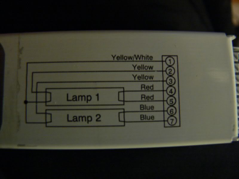
Does U-shape drawing on the lamp mean I should use a jumper wire or why do 4-5, 6-7, etc. cross-over at the bulb they way it's shown?
And for connection 2, see how it goes off to the left and form a dot - does that just mean I should splice it with wire # 1?
Last question, while the dimmable interface has a grounding wire slot that requires a grounding wire from the ballast - the ballast itself has no slot for a ground wire connection. Should I just leave it empty? |
Terminal 1 needs to be bugged together as indicated by the black dot from bulb one to bulb two. Look at the picture two dimentional, those black lines go into the stand offs as you would be looking at them from the top down.
4.5.6.7 go to the respective areas in the standoff
By All means Ground the Ballast, run the ground from the ballast to ground on the to the ground for the Power. In Other words you need to ground the ballasts at the anchor point where you fasten them. Pay attention to your local electrical codes. you may not be allowed to do it this way. When In Doubt, Contact a Local electritian.